LSC motivated SUS Requirements
On this page is a collection of Matlab modeling results concerning the DARM LSC loop and
the force requirements that these loops place on the SUS electronics in terms of range and
noise.
This, so far, does not include any of the other LSC loops, the ASC loops, or any modeling based
on locking different configurations (single arm, DRMI, etc.). The single arm case is probably
important to look at since it requires driving the ESD but in a situation where the sensing noise
level is quite high.
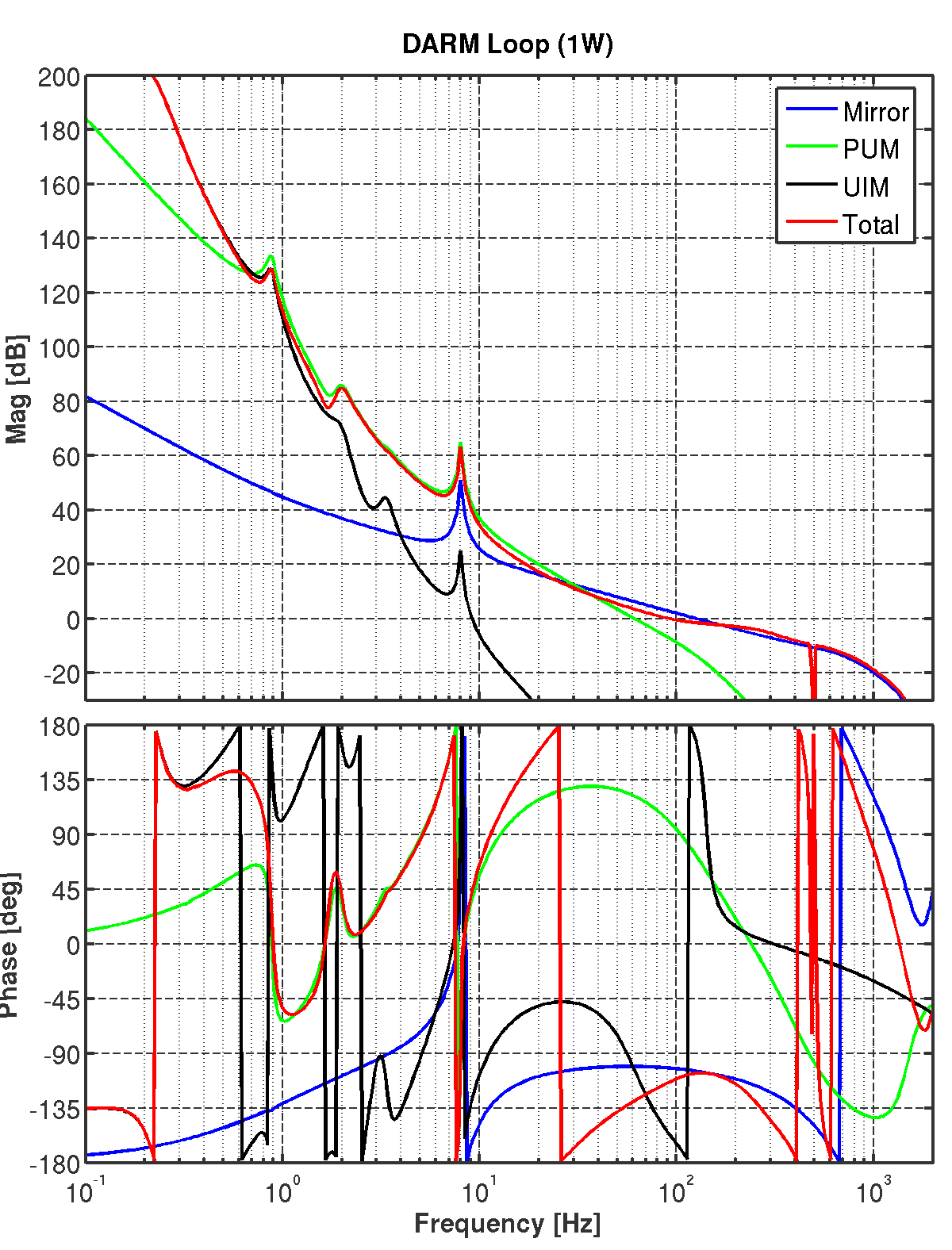
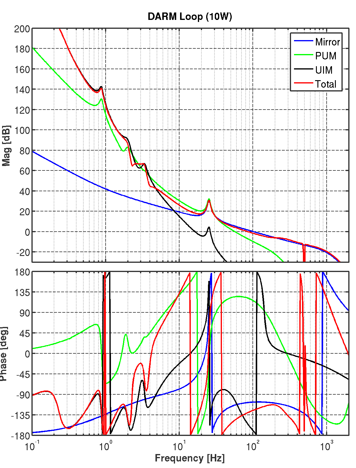
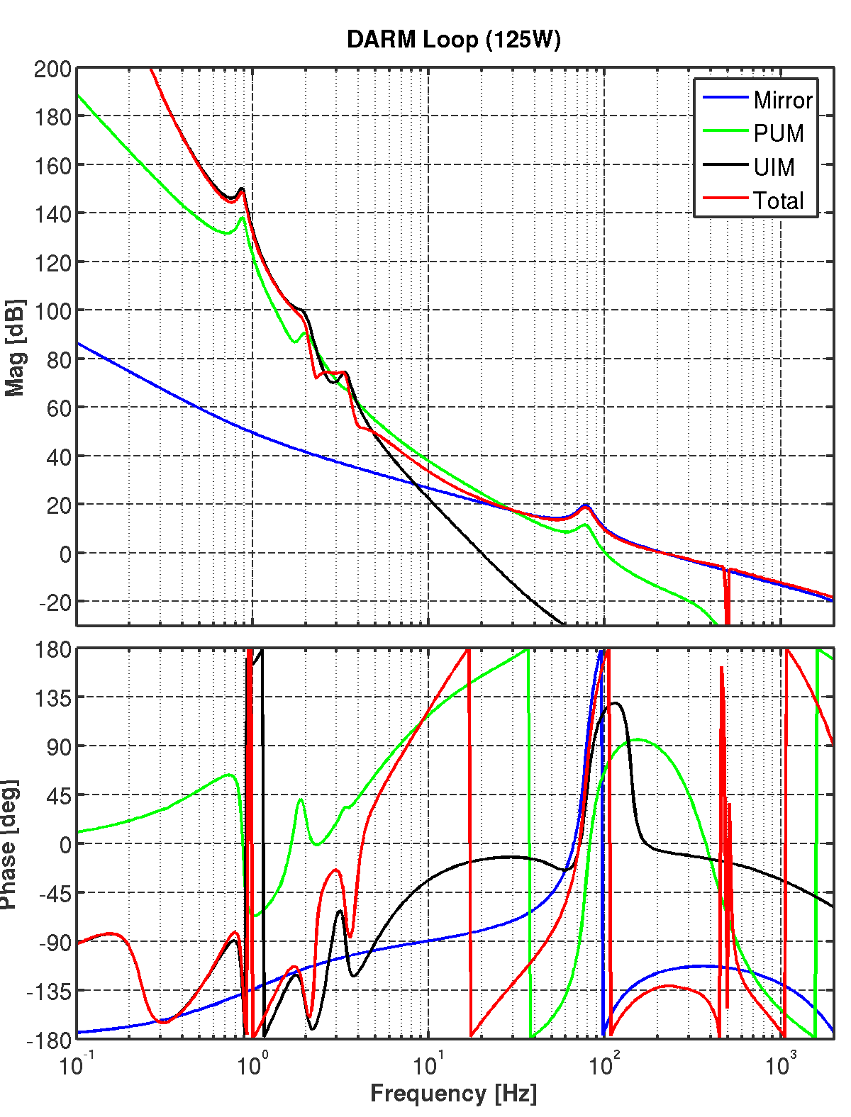
DARM Loop
This is a first stab at a differential arm length loop design using the latest quad
Simulink model. Here, I am using a set of resonant damping filters for the pendulum
modes and some aggressive elliptic low passing to get the OSEM noise out of the way
by 10 Hz.
The SUS violin modes are not included in the mechanical model, but they are
notched out in any case to simulate the real loss of phase margin. Also
included in the model are anti-liasing on the ADCs & DACs.
The optical spring dynamics are now included in the modeling for all power levels.
So in addition to the additional stiffness seen by the control system, all of the displacement
noise sources are also suppressed by the spring (thermal noise, gravidy gradients,
radiation pressure, etc.). Seismic noise is handled slightly differently; the quad model
is modified with the optical rigidity and so the resulting ground to test mass transfer
function is used (i.e. seismic noise propagates down the suspension chain rather than go directly
to the test mass).
More on Current Noise
In the above plots of the current noise in the three states, several assumptions have
been made:
For longitudinal controls, 4 OSEMs for the PM and UIM; 3 for the TOP.
Including the most recent numbers for magnet size, coil form, etc., the force coefficients
used are 1.2 N/A, 1.2 N/A, and 0.026 N/A for the TOP, UIM, and PM, respectively. These are
the single OSEM force numbers.
The 150 mA-pk requirement for the TOP mass coils assumes we will use this one for the
angular bias controls and not offload any of it onto the UIM or the SEI system. Therefore,
the requirement is the same in all 3 states.
Also have assumed that the local damping current is negligible w.r.t. the bias current
contribution.
DARM signals are the most important ones. This assumption discounts the contributions of the
WFS, optical lever, and MICH/PRC/SRC servos on the ETM control signals. These signals will be
somewhat larger than the DARM signals. We need further modeling on this.
For the control signals I have counted on two ETMs (the plots are the single coil req.).
For the noise I assume that the noise from each coil is uncorrelated with the other coils.
For the TOP, I've assumed a geometry like the UIM and so the noise estimate is a little
conservative (~20%).
Since the Gravity Gradient noise level at 10 Hz is very uncertain, I've removed it from the
budgeting. This then makes the strain noise (for the BH/BH tuning) ~10^-22 /rHz @ 10 Hz. This
is then still a factor of several above our seismic noise requirement.
To make the technical displacement noise from each quad be less than 10^-20 m/rHz @ 10 Hz,
we have to place stricter requirements than what would be determined by these plots.
For concreteness, we let each stage of the quad contribute 1/sqrt(4) of the total noise and so
this requires a net noise requirement of 0.5 x 10^-20 m/rHz from each stage. These stricter
numbers are included below in bold.
The UIM noise spec has been relaxed by a factor of 2 from the above calculation since it
looks like it makes the difference between hard and easy. In general, I think we should
consider these requirements to be a little soft and have discussions about changing
them a little down the road if it looks like it would save alot in complexity or cost.
Figure 1: Current Range Requirements
| |
TOP |
UIM |
PM |
| Noisy RMS (mA) |
? |
0.2 |
1.5 |
| Noisy Pk (mA) |
150 |
4 |
30 |
| Noisy Acq (mA) |
- |
10 |
400 |
|
| 10W RMS (mA) |
- |
0.025 |
0.200 |
| 10W Pk (mA) |
150 |
0.5 |
4 |
|
| 125W RMS (mA) |
- |
0.025 |
0.010 |
| 125W Pk (mA) |
150 |
1 |
0.4 |
Figure 2: Current Noise Requirements
| |
TOP |
UIM |
PM |
| Noisy: 1 Hz (nA/rHz) |
100 |
100 |
1000 |
| Noisy: 10 Hz (nA/rHz) |
3 |
0.3 |
1 |
| Noisy: 100 Hz (nA/rHz) |
1000 |
1000 |
1000 |
| Noisy: 1000 Hz (nA/rHz) |
1000 |
1000 |
1000 |
|
| LOW F: 1 Hz (nA/rHz) |
1 |
0.5 |
20 |
| LOW F: 10 Hz (nA/rHz) |
0.1 (0.073) |
0.01 (0.003) |
0.02 (0.004) |
| LOW F: 100 Hz (nA/rHz) |
1000 |
1000 |
50 |
| LOW F: 1000 Hz (nA/rHz) |
1000 |
1000 |
1000 |
|
| 125 W: 1 Hz (nA/rHz) |
1 |
0.5 |
20 |
| 125 W: 10 Hz (nA/rHz) |
0.1 (0.073) |
0.01 (0.006) |
0.02 (0.004) |
| 125 W: 100 Hz (nA/rHz) |
1000 |
200 |
5 |
| 125 W: 1000 Hz (nA/rHz) |
1000 |
1000 |
1000 |
In the above noise plots, one can see that because of the noise filtering action of
the quad, the force noise requirements on the upper stages are very lax and there
is no practical requirement on current noise, from the standpoint of excess
displacement noise. In those cases I have just arbitrarily set the requirement to
be 1 uA/rHz since that seems like a fairly easy level to meet.
Practically, the noise above 30 Hz may need to be larger than the 10-30 Hz requirement
to allow for the larger control signals in the 100-8000 Hz band.
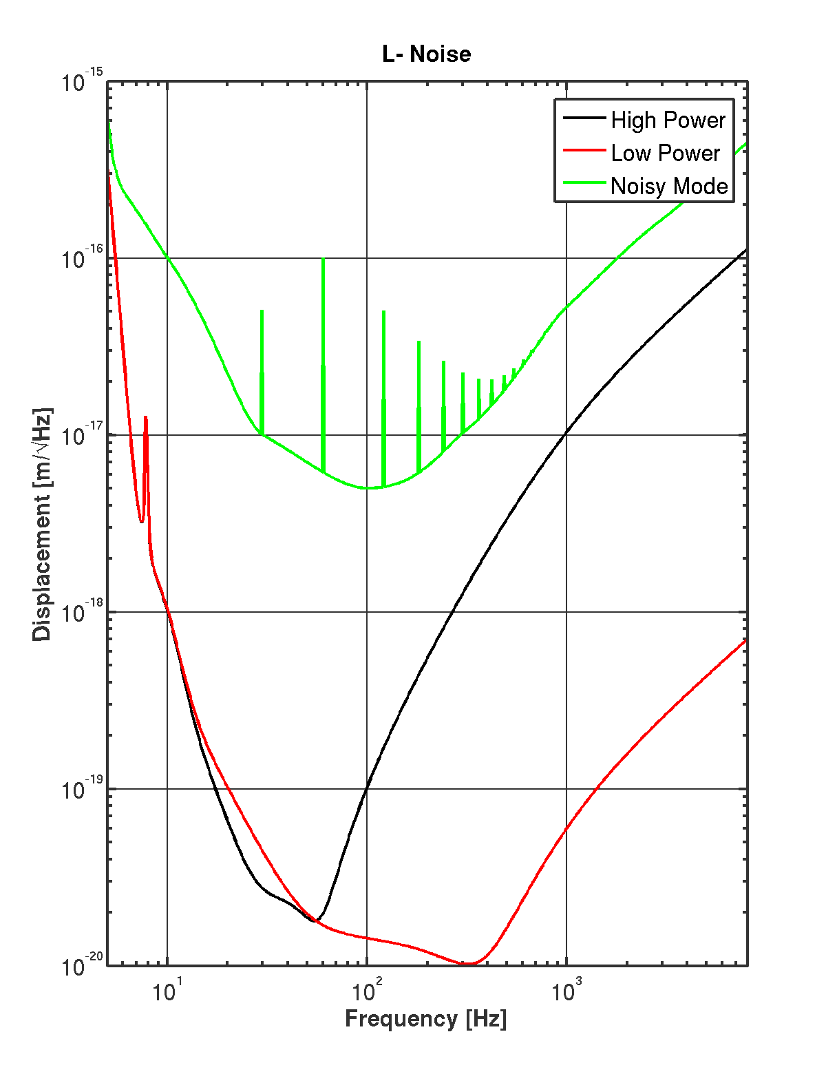
L- Noise
The plot below has a nominal noise curve from Bench, using 125 W input power
(High Power) and 25 W (Low Power). The green trace is a first guess at the
noise on the 'first day'. This is quite a bit noisier than the initial LIGO
design sensitivity but probably not crazy for how things might look before
we get the entire system commissioned.
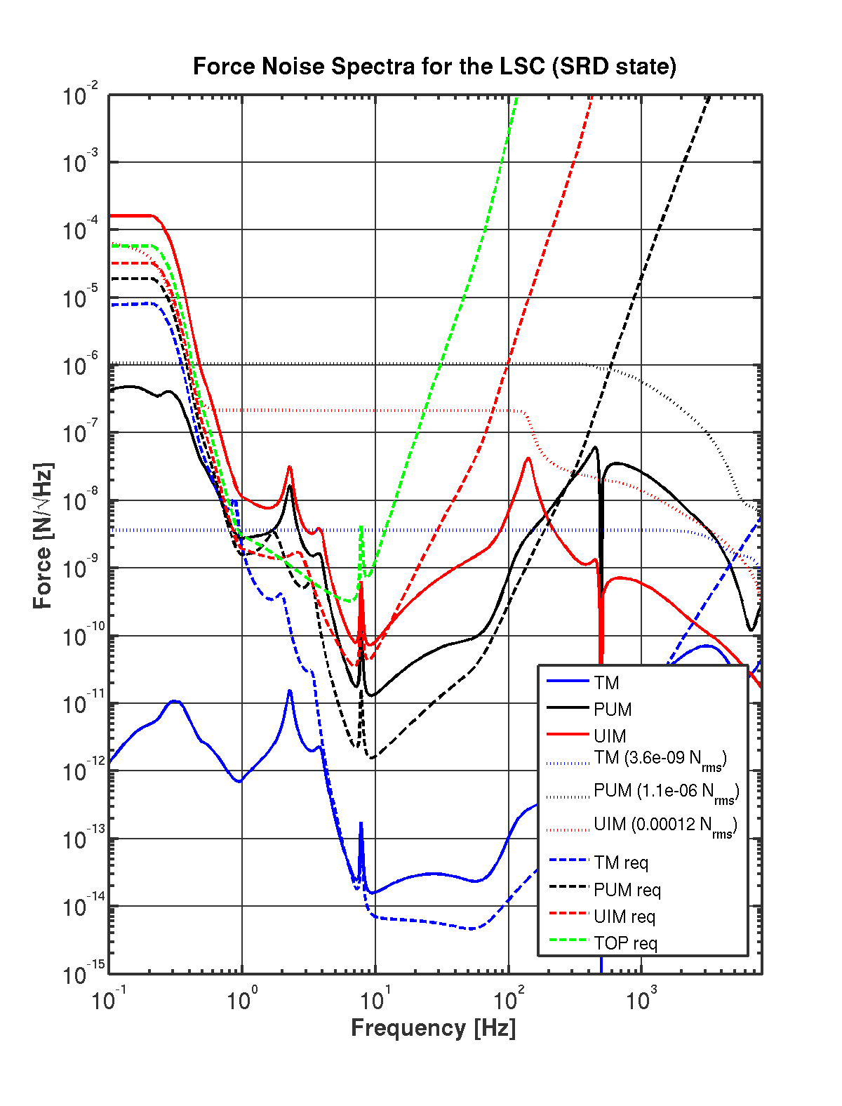
L- Noise (125 W)
Combining the L- noise and the quad model and the LSC loop model, in this plot I've
calculated the force noise spectra at each stage of the pendulum.
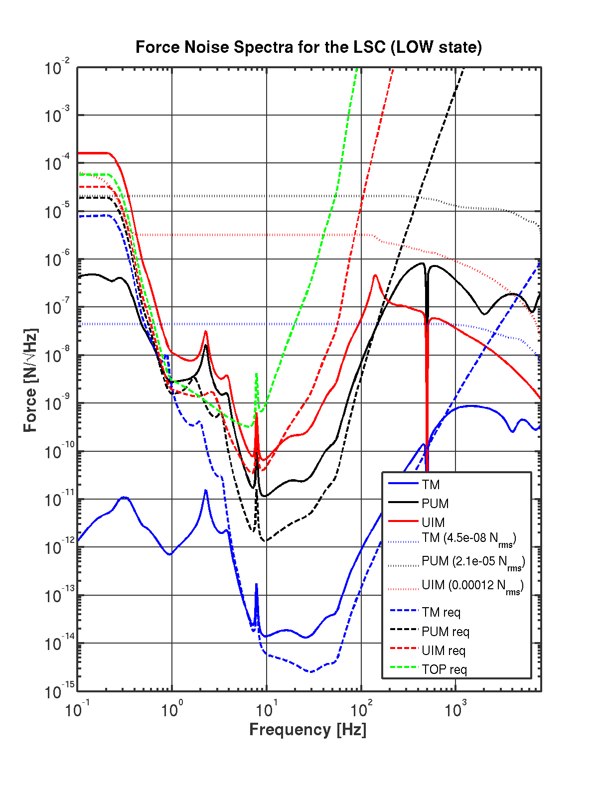
L- Noise (10 W)
Same as above, but here using the 'low power' state to calculate the control signals.
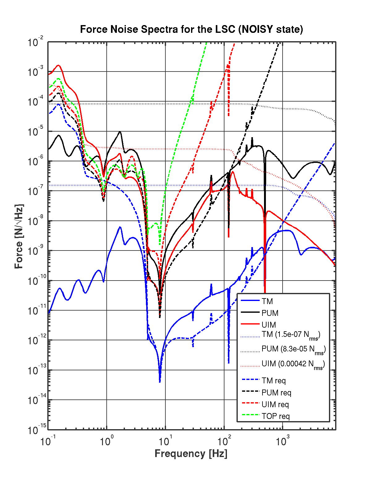
L- Noise (Noisy)
It is likely that during the early phases of commissioning and later, when taking
science data in a low power, low frequency mode, that the sensing noise above 100 Hz
will be higher by 1-4 orders of magnitude.
I propose that we require the SUS electronics to have enough range in some kind of
quasi-detection mode that allows us to run at the 'noisy' level (green trace above)
during the initial commissioning period. This is to avoid a repeat of the LIGO-I
experience of making ill-conceived field modifications to accomodate other unknown
noise sources in the detector.
The plot below shows the force noise spectrum for such a state. I leave it all in terms
of Newtons so that we can choose the magnet size / ESD bias to accomodate both the
design sensitivity and the 'noisy' state by using some appropriate switching circuits.
The 'NO ESD' Option
Of course, with the force requirements for the ESD being so small in the 2 low noise states
a natural question is why should we run the ESD at all at that point?
In the following plots I show what the loop shapes and control signals would look like if
we turn off the ESD. Of course, this will not work until we are within a factor ~10 of the
design sensitivities and the ESD would always be useful until we transition to a low noise
state.
Shutting off the ESD requires much more force on the PUM since it now must stabilize
the loop. However, its quantitatively not that bad. At the full high power tuning, the
optical spring is at almost 100 Hz, requiring a ~200 Hz UGF. With some moderate filtering
the RMS force required on the PUM is still only ~0.1 mN.
SUS Related Documents
K. Strain talk on ESDs
P.F. Considerations on Magnets
K. Strain on UIM \& PUM actuators